Goetz Romahn's Homepage
Receiver
Last updated 2005-1-23
The first HRPT receiver I constructed consists of two main
components:
Downconverter and Receiver
Downconverter
For HRPT reception I use the downconverter
developed by Radek Václavik. A kit may be purchased from
Miroslav Gola. This downcoverter is easy to construct, easy to
align and very sensitiv. Kits are not too expensive ( you could
say cheap ). Frequency translation is from 1691 MHz to 137.5
MHz only.
In addition I also do own a downconverter published in UKW-Berichte ( VHF-Communications )
developed by Bernd Bartkowiak some 15 years ago and sold as a
kit . This converter is a two-channel converter for input
frequencies of 1691 MHz and 1694.5 MHz. Since this converter
does not work as well for HRPT/HRI reception I use it only for
Meteosat APT. May be some gain is missing in ther receiver
chain since noise should not be a problem when using a good
preamplifier.
Receiver
My first ( and still most versatile ) receiver is the HPR137,
designed by Jaap van Rotten and Arne van Belle. Special parts (
eg. coils, SAW filter, tuner module etc. ) are available from
Barend Hendriksen.
The printed circuit board I got from Hans Beukinga (sorry no longer available from him).
I made some modications to the power supply by including a DC/DC converter
to generate the 33V tuning voltage needed and to the ZetF
channel switch. This switch circuit I replaced meanwhile by
a PIC microprocessor
controlled switch which is in addition to switching
receiver channels also capable to switch my Alblas C-HRPT/PDUS
decoder to its proper operating mode accordingly.
Schematic if the PIC controlled channel switch ( click to
enlarge).
You will find all the necessary details for construction and
programming of the PIC with source codes included on my download page. I also
included means for remote control via RS232 serial line ( line
speed 19200bps ). An associated DOS utility program for
testing or to select channels via a serial port is also
available.
From a user point of view this controller is fully compatible
with my PIC controller used with the RIG HRPT receiver ( see below ). So if you
got your mouth watered by reading Bob Barnes article in
RIG-Journal VOL. 71 to set up a fully batch controlled HRPT
station by using David Taylors Wxtrack software, this will be (
and is in my system ) also possible with the "Kunstmaanen"
receiver.
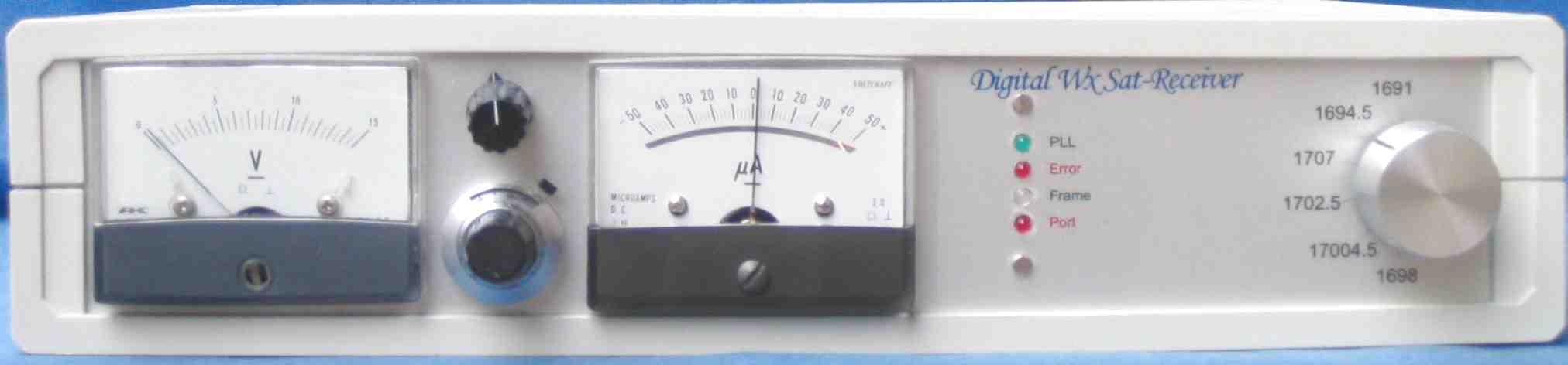
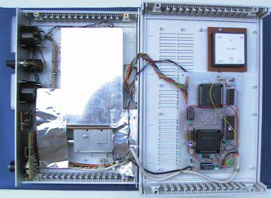
I put my HPR137 receiver and Alblas decoder into the same
enclosure ( for an open view see below ). On the left side you
see the bottom part of the open enclosure with receiver in a
metal box an the tuner module mounted to its lower side. The
channel switch, some status LEDs, field strength and tuning
meters are monted to the front panel ( left side of the picture
). Part of the wiring needed some extra screening due to the
neighbourhood of the digital decoder module when lid is closed.
On the right side you see an inner view of the lid with decoder
and DC/DC converter, to provide -12 Volt for the receiver,
mounted. When looking at the front panel, you may be
missing channel select switches and corresponding indicator
LEDs from the decoder. I do not have and never missed them
while using Alblas HRPT software. There are also no "mode
switches" to switch Alblas decoder from HRPT to either CHRPT or
PDUS mode and back again, since this is done automagically by
my new PIC controlled channel switch ( see above).
This receiver is now in regular use at my home for receiving
HRI transmissions from Meteosat 7. With my 135cm prime focus
dish antenna and a Vidmar preamplifier I receive nearly speckle
free pictures 24h hours a day ( the nonencrypted of course ).
For an example see my images page.
HPR137 front panel
HPR137 inside view, receiver board in metal can on the left,
Alblas decoder bord botton right
In summer 2002 I complemented my receiver equipment by
constructing the RIG HRPT receiver developed by Sam Elsdon
and available for members as a kit from RIG. Details of
adventures during construction and about some modifications I
made will be described below
Sam Elsdon's RIG HRPT receiver
before continuing to my notes I want to point out that I am
not !! going to blame somebody, especially not Sam Elsdon. I
sent him my notes and he commented carefully to all of them.
Thank you Sam, thank you for this interesting design and thank
you to the RIG-team for making this KIT available.
1. Kit arrived complete with all parts included. Perfect
!!
2. While constructing the RX following the step by step
method from Sam's manual, I had a problem: the PLL did not
lock. After a long search that needed a spectrumanalyzer to
identify signals, I detected a short circuit between pins 7 and
8 of the premounted synthesizer IC. I removed that carefully
under a magnifier by using a very sharp knife ( actually a
scalpel ). Now the PLL worked as expected -- occasionally ! The
reason was a bad contact of pin 16 to the power supply. I
seems, that this IC had been misaligned during fitting to
PCB.
3. Further construction proceeded smoothly, thanks to the
manual.
4. The programming error of Fengyun frequencies in the first
release of PIC software Sam already detected and corrected. It
is also corrected in my modified software. See below.
5. One problem still remained: there is a drift in the
demodulator PLL that makes the RX rather difficult to use. See
Sam's
website for any countermeasures.
6. To handle the drift problem I did the following ( see excerpt of
schematic ) :
- I added an adjustable voltage via 15 kOhm to pin 6 of U13B.
So I can finetune the VCO frequency from the frontpanel.
- to gain some feedback I connected a zero indicator
instrument to the I and I_ pins ( +- 100uA indicator with an
internal resistance of 1750 Ohm ). Connecting this instrument
did no harm to the signal quality.
- additionally I developed a lock indicator by connecting an
op amp to the Q and Q_ outputs of the demodulator similar to
U13B beeing connected to I and I_ . The signal level for
lock-detect is determined by adding an adjustable voltage to
the inverting input of that op amp. The output of the op amp is
connected to an LED. This lock detector has proven to be very
sensitive -- signals are detected when the S-meter does not
even move a little -- and reliable. So one may omit the zero
indicator mentioned above ( I did not, I like it very much
)
7. R15 from the schematic is 1k, a rather large value. I
added another 1k in parallel resulting in 500 Ohm. This gives
higher gain and better large signal performance.
8. I migrated the controller software from PIC16c54 to
PIC16F84. For this to work at least R7 should be >5k and C17
abt. 100pF.
9. I added Meteosat frequencies of 1691 MHz and 1694.5 MHz .
This makes it possible to use Meteosat as a beacon for testing
the whole system and (!!!) for fine tuning the demodulator VCO
frequency with a stable reference frequency. I would strongly
recommend to put in Meteosat frequencies into the next release
instead of the unused 1704.5 and one 1707 channels.
BTW I received HRI pictures from Meteosat with this RX and an
135cm prime focus dish antenna with only few speckles and bad
lines. Sourcecode for this minimal modification
with migration to 16f84 and Meteosat 7 frequencies is available
here. Do not forget the necessary modifications of point 8.
10. The PIC software has been modified additionally to have
serial input for remote control instead of the time-step
interface and control of the Alblas decoder settings for the
various data formats of the different satellites. This
modification results in a single switch operated receiver for
HRPT, C-HRPT and HRI ( less VCO fine tuning ). Source code for this
with an associated DOS utility program to
select channels via a serial port is also available. Some modifications
to the hardware need to be done for this software to work
also. Since I am not going to use time-step remote control I
removed the resistor network R12 and cut pin 20 of U5 .
Connector J3 now has spare pins which I use to connect to the
serial port and to the Alblas decoder.
11. The IF chain with L3 and L4 needs slightly different
settings for HRPT and C-HRPT, so you have to find some
compromise.
You will find a complete package of my amendments to the
RIG HRPT receiver on my download page.
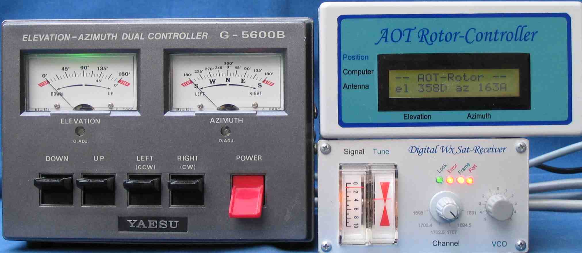
What have I achieved so far ?
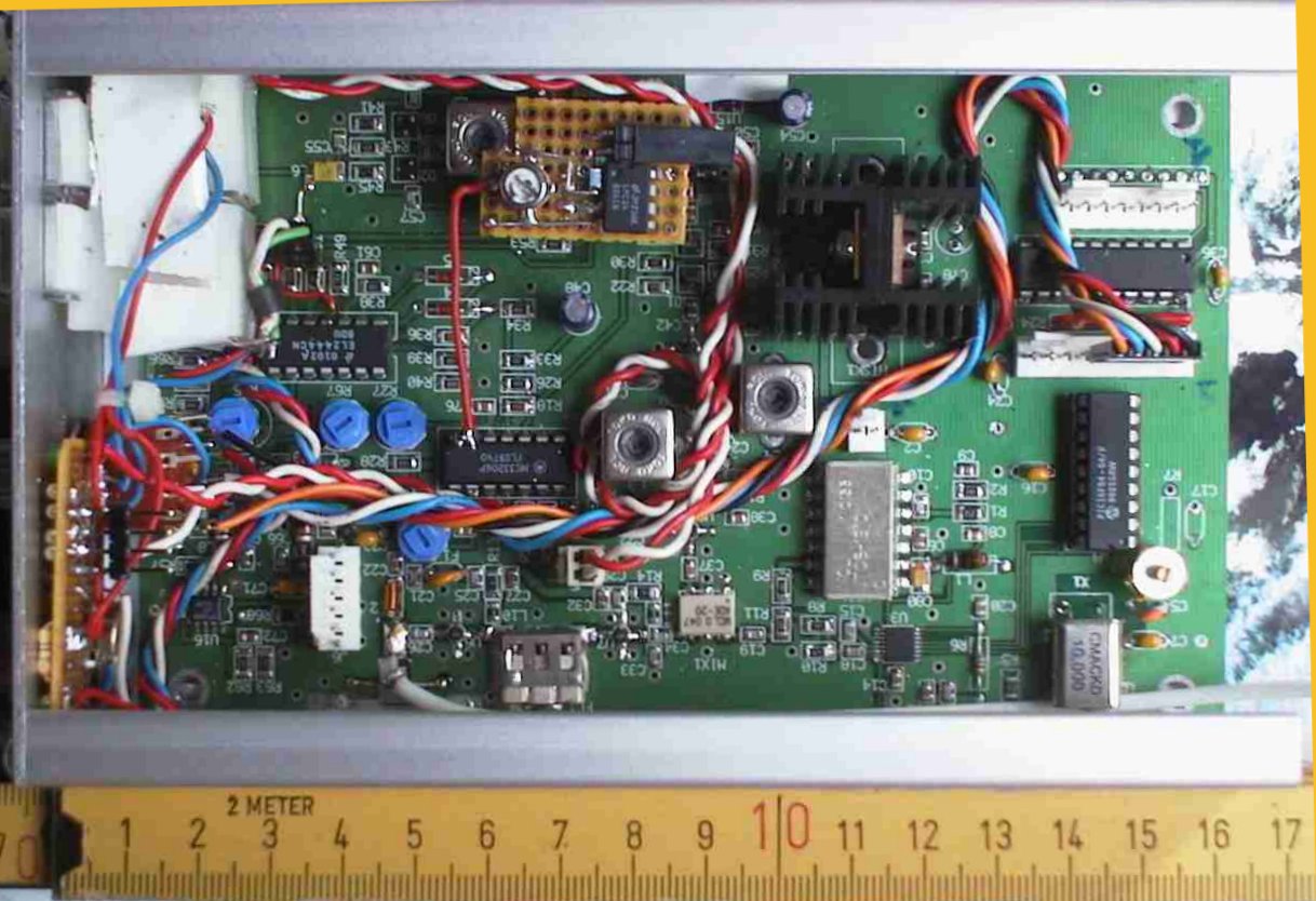
I tried to assemble a very small HRPT receiver station ( the
second smallest of the world ?) also good for mobile use with
+12V battery power. To achieve this I squeezed the RIG HRPT RX
and my Alblas decoder board into a single small aluminium box (
see pictures below, meter scale is centimeters not inches ). On
the front panel I have meters for signal strength and fine (
zero) tuning as well as indicator LEDs to show demodulator
lock, bit errors, frame-sync and LPT-port status, channel
select switch and frequency fine tuning. At the rear panel are
connectors for PC-LPT port, serial port for remote control,
C-HRPT eye signal output, RF-input from antenna preamplifier
and +12V DC.
Complete setup with RIG HRPT receiver at botton right
The picture below is a top view to the open box with decoder
board removed. I used a smaller heatsink for the power
regulators than the original. The perfo-board contains the lock
detector. It is mounted piggiback to the PCB riding on some
jumper posts. Cable has been given some added legth, so the
unit can be disassembled for testing purposes. Since my "bad lines problem"
with my Alblas decoders have been settled recently, all nuts
and bolts have been securely fastened and this receiver is in
regular use at my home.
 Back
Back